

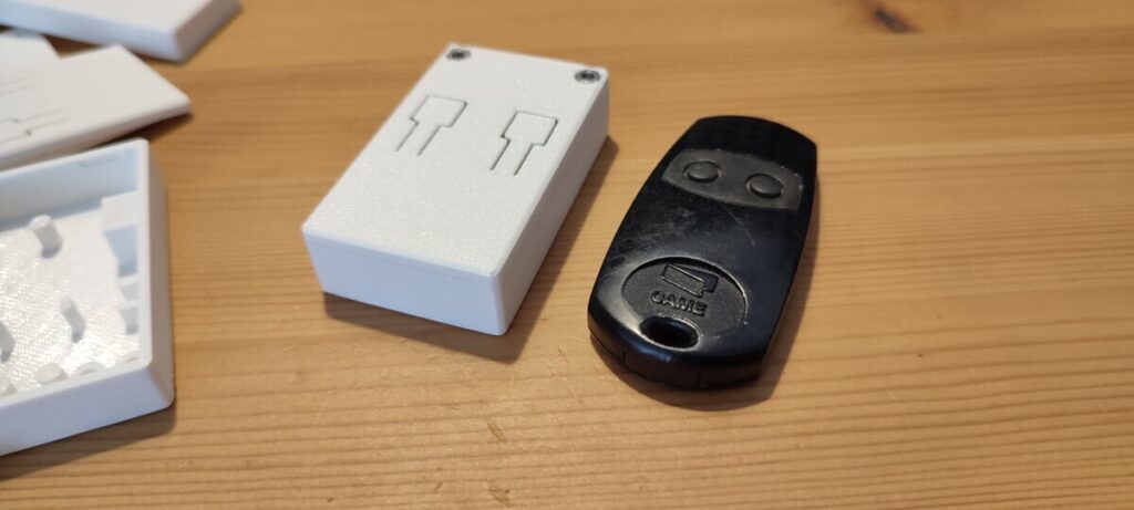
A family member mentioned that she had a broken key fob for her garage door, in which the left button was inoperative. It seemed very likely that the switch itself was broken, so I offered to replace it.
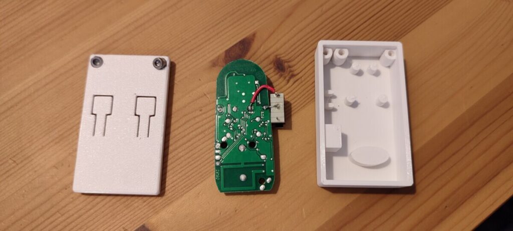
However, I did not have time to source a new switch, so I opted to wire a microswitch in parallel and design a new case that would fit the original PCB with the new switch.
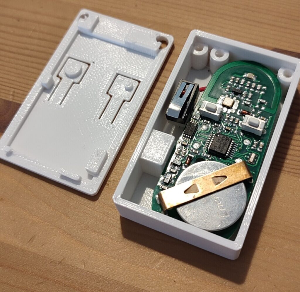
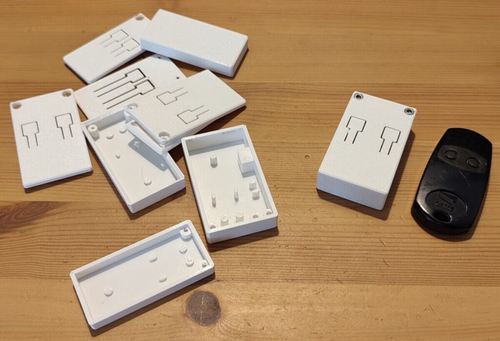
The various posts hold the PCB circuit horizontally and laterally, and the holes are designed to accept self-tapping cap head M3 screws. The lid has recessed compartments so the screw heads don’t protrude at all.
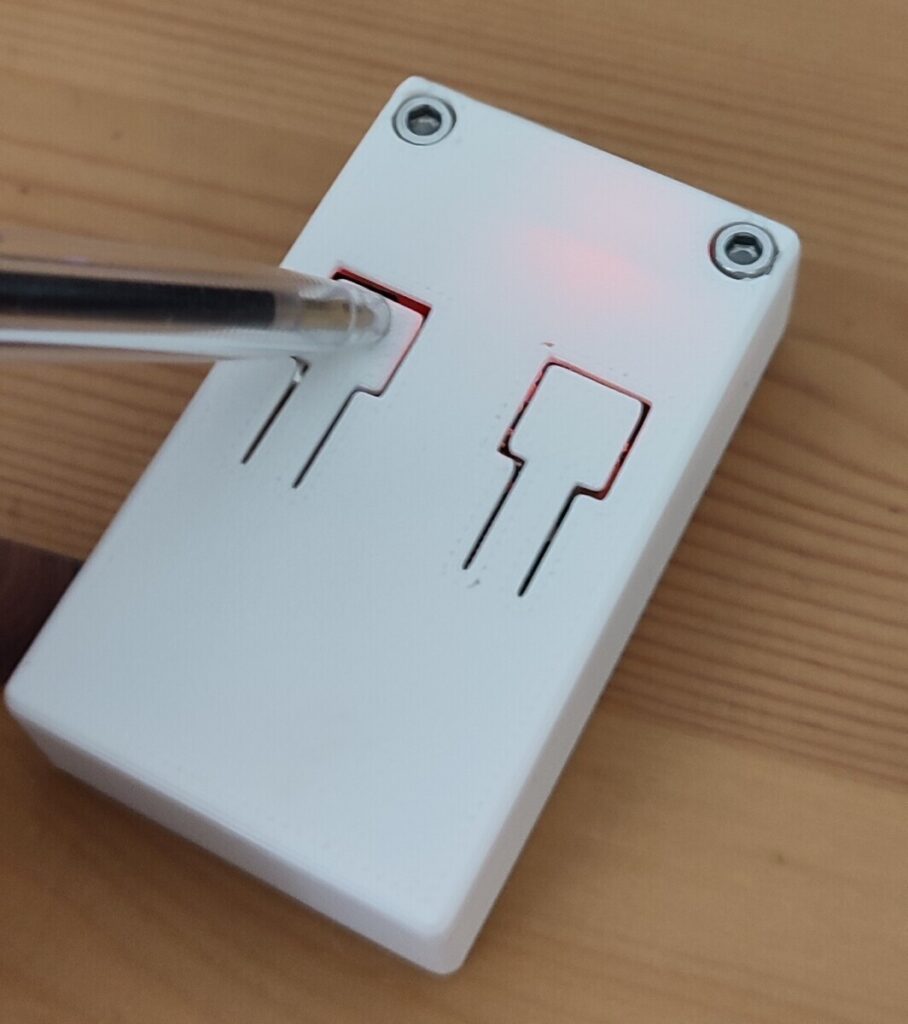
The source and print files are available at PrusaPrinters.